
 Business License

Custom mold drawing and tolerance requirements for buyers
A custom mold arrives after eight weeks of tooling work. The first trial parts come off the press, and the snap-fit housing will not close. The drawing never specified the gap tolerance, so the mold maker used a general workshop standard, and now the mold needs rework at your expense. Most custom mold disputes trace back to exactly this gap between what the buyer assumed and what the drawing actually said.
If you are researching custom mold drawing and tolerance requirements, you probably already know that a mold is only as good as the information behind it. Unlike standard industrial equipment categories, a custom mold is built to your part, your material, and your production process. The mold maker cannot guess your fit requirements, your assembly conditions, or your quality expectations.
This guide walks you through the custom mold drawing and tolerance requirements that decide whether your enquiry produces an accurate quotation and a working mold. You will learn what a complete drawing package contains, how to specify tolerances without overspending, what information beyond the drawing matters, and which mistakes to avoid. Every recommendation follows one principle: the clearer your documentation, the more accurate your quotation and your mold.
What drawings are needed for a custom mold enquiry?
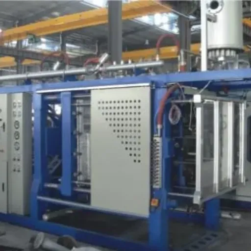
A custom mold enquiry needs a 2D part drawing with dimensions, tolerances, and critical features marked, plus a 3D model in a neutral format such as STEP. Include the part material, expected production volume, surface finish requirements, and any assembly or fit conditions. Clearer drawings produce faster, more accurate mold quotations.
Why drawings and tolerances decide the outcome
A mold maker quotes and builds from your documentation, not from your intentions. Every undefined dimension becomes an assumption, and assumptions in tooling are expensive. A missing tolerance can mean a mold built looser than your assembly needs, or tighter than your budget allows.
Tolerances also drive the price directly. A tighter tolerance requires more precise machining, more fitting work, more measurement, and often more expensive mold steel and finishing. When you tighten a tolerance, you are spending money, so the decision should be deliberate rather than default.
Here is an illustrative example. A product engineer we will call Kenji sent a 3D model of a two-part plastic housing to three mold makers without a 2D drawing or tolerance callouts. The quotations came back 40% apart, because each supplier had assumed different tolerance levels.
Worse, the lowest quote assumed general workshop tolerances that his snap-fit design could not tolerate. After he issued a proper drawing with critical dimensions marked, the three quotations converged within 8%, and the chosen mold produced parts that assembled on the first trial.
Note: Tolerance values, costs, and timelines in this article are illustrative. Confirm every requirement against your part design and the mold maker's current documentation.
The lesson generalizes: undefined requirements do not make a quotation cheaper, they make it incomparable. If you want a supplier to review your documentation package, you can discuss your custom mold requirements once your drawings are prepared.
What a complete custom mold drawing package includes
Mold makers work best from a combination of 2D drawings and 3D models. Each serves a different purpose, and a complete package prevents most downstream disputes.
The 2D part drawing
The 2D drawing is the contractual reference. It should show all views needed to define the part, with every dimension stated in consistent units. Mark the following clearly:
Critical dimensions: The dimensions that decide fit, function, or safety, each with its own tolerance.
Datum references: The surfaces or features from which other dimensions are measured, so inspection matches design intent.
Wall thickness: Nominal thickness and any areas where thickness varies, because this affects mold design and part quality.
Draft angles: The taper that lets the part release from the mold. If your design fixes them, state them; if not, ask the mold maker to propose them.
Gate and ejector restrictions: Areas where gate marks or ejector pin marks are not acceptable, such as visible surfaces. These details belong on every injection mold drawing, because they directly shape the tool design.
Parting line preferences: Where mold halves may meet, and where a parting line would be cosmetically or functionally unacceptable.
The 3D model
Provide the 3D model in a neutral format such as STEP, which most computer-aided design (CAD) systems can read reliably. A native file from your design software is a useful addition but should not be the only format. Confirm that the 3D model and the 2D drawing match, because mold makers typically treat the 2D drawing as authoritative when the two disagree.
Material and surface information
State the exact molding material, including grade where possible. Material choice determines shrinkage behavior, and the mold maker uses the documented shrinkage rate of the specific material to scale the mold cavities. Also state surface finish requirements, such as polished, textured, or standard machined surfaces, and any areas with cosmetic requirements.
Revision control
Give every drawing a revision code and date, and reference that revision in your enquiry.
In our second illustrative example, a procurement officer we will call Omar emailed a mold maker an updated drawing but referenced the old revision code in the message. The supplier built to the drawing archive they had on file, which was one revision behind. The mismatch surfaced at the first article inspection, and the correction cost both time and goodwill. A revision code on the drawing, in the file name, and in the enquiry email takes seconds and prevents the entire class of error.
How to specify tolerance requirements for a custom mold

Tolerance specification is where buyers most often overspend or underspecify. Both errors are avoidable with a simple discipline: tight where it matters, general everywhere else.
Distinguish critical from non-critical dimensions
Go through your part and mark which dimensions genuinely control fit, function, sealing, or safety. Give each of those an explicit bilateral tolerance, such as ±0.05 mm. Everything else can follow a general tolerance standard, which you state once in the drawing title block.
Mold tolerance standards provide a documented default so the supplier does not have to guess. A widely used option for general tolerances on machined and molded features is the ISO 2768 series, which defines tolerance classes from fine to very coarse. The International Organization for Standardization publishes this and related geometrical product specification standards; see iso.org for the current editions. Stating "ISO 2768-mK applies unless otherwise specified," or an equivalent class appropriate to your part, gives the mold maker a documented default instead of a guess.
Use geometric tolerances where shape matters
Some requirements are about form rather than size: flatness of a sealing face, position of a mounting hole pattern, or perpendicularity of mating surfaces. Geometric dimensioning and tolerancing (GD&T) provides standard symbols for these requirements. The ASME Y14.5 standard from the American Society of Mechanical Engineers is the common reference; see asme.org for current information. Use GD&T on the features that need it, with datums defined, rather than writing ambiguous notes like "must be flat."
Understand the shrinkage chain
Your drawing defines the finished part. The mold must be built larger, because plastic shrinks as it cools. The mold maker applies the material's documented shrinkage rate, taken from the material's technical datasheet, to convert part dimensions into cavity dimensions. This is why the exact material grade belongs in your enquiry: different grades of the same polymer family can shrink differently, and a cavity sized for the wrong shrinkage rate produces out-of-tolerance parts no matter how precisely it was machined.
Avoid over-tolerancing
In our third illustrative example, a buyer we will call Ruth specified ±0.01 mm on every dimension of a simple enclosure, including decorative outer surfaces. The quotation came back nearly double her budget, because every dimension now required precision machining and individual verification.
Her engineer reclassified the drawing: four functional dimensions kept tight tolerances, and the rest moved to a general tolerance class. The revised quotation dropped by roughly a third, and the parts still met every assembly requirement. Precision is a tool; apply it where it pays.
Ready to prepare your package? Gather your 2D drawing, 3D model, material grade, and tolerance scheme, then request a quotation with the complete documentation attached.
Information beyond the drawing that mold makers need
A drawing defines the part, but a mold is production equipment. The mold maker also needs the production context to design the tool correctly:
| Information | Why it matters |
|---|---|
| Expected production volume | Determines mold steel, cavity count, and durability class |
| Molding machine or process | The mold must match the machine's clamping force, platen size, and nozzle |
| Part material and grade | Drives shrinkage allowance, corrosion resistance, and surface treatment |
| Cycle time expectations | Influences cooling channel design and cavity count |
| Destination market | Affects documentation language and any applicable requirements |
| Assembly and usage conditions | Identifies which features are truly critical |
This table reflects common industry practice, not a universal requirement list. Confirm exactly what your mold maker needs for the specific project.
Two points deserve emphasis. First, if you already own the molding machine, share its model number and key parameters, because a mold that does not fit your press is scrap metal. Second, if the mold will run on the supplier's equipment or a third party's, state that clearly so the design targets the right machine class.
Common mistakes in custom mold enquiries
Experience across custom tooling projects shows the same recurring errors. Check your enquiry against this list before sending it:
Sending only a 3D model. Without a 2D drawing, tolerances, materials, and critical features are undefined.
No tolerance scheme at all. The supplier guesses, and each supplier guesses differently, so quotations cannot be compared.
Tight tolerances everywhere. This inflates price without improving function; classify critical versus general dimensions instead.
Missing material specification. Shrinkage, steel selection, and surface treatment all depend on the exact material.
No revision control. Suppliers may build to an outdated file; label every revision on the drawing and in the message.
Forgetting the production context. Volume, machine, and cycle expectations shape the mold design as much as the part geometry does.
Assuming the mold maker owns design risk. Ambiguities in buyer documentation usually become buyer costs; resolve questions in writing before tooling starts.
Confirm documentation and commercial terms before ordering
Before you commit to a custom mold order, confirm the following in writing for the specific project:
Design review process: Whether the mold maker provides a mold design drawing for your approval before cutting steel, and how design changes are handled.
Trial and sampling terms: Whether trial shots and sample parts are included, how many, and who approves them.
Measurement reporting: What inspection reports accompany the trial parts, such as dimensional reports against your drawing.
Mold ownership and storage: Who owns the mold, where it is stored, and what maintenance or repair arrangements apply.
Commercial terms: Quotation scope, payment milestones, lead time, delivery terms, and warranty or rectification arrangements.
Documentation: The drawing register, mold documentation, and any certificates relevant to your destination market.
Suppliers that work with international buyers, including XiAn Wisdom Computer Info&tech Co., Ltd, typically expect this kind of structured enquiry. The company lists molds and PVC molding machines among its product categories and states that quality management and after-sales support are central to its service approach. As with any supplier, confirm project scope, documentation, and service terms in writing before ordering. A technical documentation guide can help you structure those requests, and an industrial equipment quotation checklist helps you compare the offers you receive.
Conclusion: clear drawings, accurate molds
Custom mold projects succeed or fail on documentation quality. Keep these takeaways in mind:
Provide both a 2D drawing and a 3D model. The drawing is the contractual reference; the model supports manufacturing.
Classify your tolerances. Explicit tolerances on critical dimensions, a stated general tolerance standard for everything else.
Specify the exact material. Shrinkage rates drive cavity dimensions, and the grade matters.
Include the production context. Volume, machine, and cycle expectations shape the mold design.
Control revisions and confirm terms in writing. Most tooling disputes start as documentation gaps.
Your next step is practical: review your current part documentation against the custom mold drawing and tolerance requirements in this guide, close the gaps, and then send the complete package to your shortlisted mold makers.
Submit your custom mold drawings or discuss your project →
A complete documentation package gets you comparable quotations, a faster tooling process, and parts that fit the first time. Define the requirements clearly, verify them in writing, and the mold will follow.
Recently Posted
-
How to request a technical quotation for industrial equipment
August 17, 2026A purchasing assistant sends a one-line email to five suppliers: "Please quote your best price for a water pump." Two we Read More
 -
What Information Is Needed for a PVC Molding Machine Enquiry
August 17, 2026A buyer who sends a PVC molding machine enquiry without the right technical details often receives quotes that cannot be compared Read More
 -
Power supply documentation checklist for industrial buyers
August 17, 2026Last March, Elena Vasquez received a shipment of frequency power supplies for a new cold-storage line. Elena is a procurement mana Read More
 -
Industrial equipment voltage and frequency requirements: a buyer's compatibility guide
August 17, 2026In March 2024, a procurement team in Dubai took delivery of a flake ice machine they had ordered from a supplier in East Asia. The Read More

Contact Us
Recommended Products
-
 Large Capacity Ceiling Mounted Space Saving Indoor Pool DehumidifierNegotiableMOQ: 1 Piece
 -
Commercial Home Use Bathroom Dehumidification Swimming Pool Ceiling Mounted Mini DehumidifierNegotiableMOQ: 1 Piece
-
Greenhouse Grow Room Industrial Ceiling Mounted Duct Indoor Pool DehumidifierNegotiableMOQ: 1 Piece
-
Duokai OEM Indoor Dehumidifier Portable Swimming Pool Dehumidifier in Stock With CENegotiableMOQ: 1 Piece
-
High Quality Low Voltage ODM & OEM PLC Distribution CabinetNegotiableMOQ: 1 Set








-
Saladin Type Malt Production LineNegotiableMOQ: 1 Set
-
Seawater Desalination SystemUS$ 2000 - 1000000MOQ: 1 Set
-
High Speed Synthetic Lane Bowling Ball ReturnUS$ 50 - 2000MOQ: 10 Pieces
-
Small Industrial 6-Axis Articulated Robot With Smart Welding System for Precise TasksNegotiableMOQ: 1 Piece
-
Collaborative 6-Axis Welding Robot Arm With Automatic MIG Welder CobotNegotiableMOQ: 1 Piece

-
Smart 6-Axis Articulated Robot Arm for Enhanced Metal Welding PerformanceNegotiableMOQ: 1 Piece
-
Industrial 6-Axis Welding Robot Arm With High Precision for Metal FabricationNegotiableMOQ: 1 Piece
-
Laser 6-Axis Articulated Welding Cobot Robot With Automatic Welding SystemNegotiableMOQ: 1 Piece
-
High-Speed 4-Axis Delta Robot With 3kg Payload, Gripper and Suction Cup for Food Packaging LineNegotiableMOQ: 1 Piece
-
4-Axis Collaborative Robot Arm for CNC Machine Tending and Automation SolutionsNegotiableMOQ: 1 Piece